The specifications serve for C-band 96 channels Flat-top MUX/DEMUX Athermal AWG module in DWDM system.
Optical Specifications

Figure 1 Optical signal transmission characteristics
Table 1 Optical Specifications
Parameters | Notes | Specifications | Units | |
Min | Max | |||
Channels | 96 | Ch | ||
Channel Spacing | 50 | GHz | ||
Reference Pass-band | Relative to ITU Grid | ± 6.25 | GHz | |
ITU Frequency | See Table 2 Below | THz | ||
ITU Wavelength | See Table 2 Below | nm | ||
Center Frequency Accuracy | Maximum of the absolute deviation of the 3 dB center wavelength from ITU grid over all channels | -0.05 | +0.05 | nm |
Insertion Loss | Maximum of the insertion loss at the ITU wavelength over all channels | 6.0 | dB | |
Insertion Loss Uniformity | Maximum insertion loss variance across all channels | 1.5 | dB | |
Ripple | Maximum of the loss variance across the ITU pass-band over all channels | 0.5 | dB | |
1dB Bandwidth | 1dB from min Insertion Loss, full width, average polarization | 0.2 | nm | |
3dB Bandwidth | 3 dB from min Insertion Loss, full width, average polarization | 0.26 | nm | |
20 dB bandwidth | 20 dB from min Insertion Loss, full width, average polarization | 0.7 | nm | |
Adjacent Channel Isolation (Insertion loss @ITU) | Maximum insertion loss difference between the highest power channel and two adjacent channels overall operating conditions such as temperature, average polarization at ITU. | 25 | dB | |
Non-Adjacent Channel Isolation (Insertion loss @ITU) | Maximum insertion loss difference between the highest power channel and non-adjacent channels overall operating conditions such as temperature, average polarization at ITU. | 30 | dB | |
Total Crosstalk (Insertion loss @ITU) | Total cumulative average insertion loss difference between the highest power channel and all other channels overall operating conditions such as temperature, average polarization at ITU. | 21 | dB | |
Polarization Dependent Loss | Maximum ratio of transmissions over all polarization states, over the ITU pass-band | 1.0 | dB | |
Polarization Mode Delay | In Reference Passband over all channels | 0.5 | ps | |
Chromatic Dispersion | In Reference Passband over all channels | -20 | 20 | ps/nm |
Directivity | 45 | dB | ||
Return Loss | 45 | dB | ||
Continuousoptical power | 500 | mW | ||
Connector is included.
Table 2 Channel Plan
First Channel Frequency (THz) | Last Channel Frequency (THz) | First Channel Wavelength (nm) | Last Channel Wavelength (nm) |
196.10 | 191.35 | 1528.773 | 1566.723 |
Table 3 Channels List: Passbands for 96 channel AAWG
Label | Frequency(THz) | Wavelength(nm) | Label | Frequency(THz) | Wavelength(nm) |
C61 | 196.10 | 1528.773 | C37 | 193.70 | 1547.715 |
H60 | 196.05 | 1529.163 | H36 | 193.65 | 1548.115 |
C60 | 196.00 | 1529.553 | C36 | 193.60 | 1548.515 |
H59 | 195.95 | 1529.944 | H35 | 193.55 | 1548.915 |
C59 | 195.90 | 1530.334 | C35 | 193.50 | 1549.315 |
H58 | 195.85 | 1530.725 | H34 | 193.45 | 1549.715 |
C58 | 195.80 | 1531.116 | C34 | 193.40 | 1550.116 |
H57 | 195.75 | 1531.507 | H33 | 193.35 | 1550.517 |
C57 | 195.70 | 1531.898 | C33 | 193.30 | 1550.918 |
H56 | 195.65 | 1532.290 | H32 | 193.25 | 1551.319 |
C56 | 195.60 | 1532.681 | C32 | 193.20 | 1551.721 |
H55 | 195.55 | 1533.073 | H31 | 193.15 | 1552.122 |
C55 | 195.50 | 1533.465 | C31 | 193.10 | 1552.524 |
H54 | 195.45 | 1533.858 | H30 | 193.05 | 1552.926 |
C54 | 195.40 | 1534.250 | C30 | 193.00 | 1553.329 |
H53 | 195.35 | 1534.643 | H29 | 192.95 | 1553.731 |
C53 | 195.30 | 1535.036 | C29 | 192.90 | 1554.134 |
H52 | 195.25 | 1535.429 | H28 | 192.85 | 1554.537 |
C52 | 195.20 | 1535.822 | C28 | 192.80 | 1554.940 |
H51 | 195.15 | 1536.216 | H27 | 192.75 | 1555.343 |
C51 | 195.10 | 1536.609 | C27 | 192.70 | 1555.747 |
H50 | 195.05 | 1537.003 | H26 | 192.65 | 1556.151 |
C50 | 195.00 | 1537.397 | C26 | 192.60 | 1556.555 |
H49 | 194.95 | 1537.792 | H25 | 192.55 | 1556.959 |
C49 | 194.90 | 1538.186 | C25 | 192.50 | 1557.363 |
H48 | 194.85 | 1538.581 | H24 | 192.45 | 1557.768 |
C48 | 194.80 | 1538.976 | C24 | 192.40 | 1558.173 |
H47 | 194.75 | 1539.371 | H23 | 192.35 | 1558.578 |
C47 | 194.70 | 1539.766 | C23 | 192.30 | 1558.983 |
H46 | 194.65 | 1540.162 | H22 | 192.25 | 1559.389 |
C46 | 194.60 | 1540.557 | C22 | 192.20 | 1559.794 |
H45 | 194.55 | 1540.953 | H21 | 192.15 | 1560.200 |
C45 | 194.50 | 1541.349 | C21 | 192.10 | 1560.606 |
H44 | 194.45 | 1541.746 | H20 | 192.05 | 1561.013 |
C44 | 194.40 | 1542.142 | C20 | 192.00 | 1561.419 |
H43 | 194.35 | 1542.539 | H19 | 191.95 | 1561.826 |
C43 | 194.30 | 1542.936 | C19 | 191.90 | 1562.233 |
H42 | 194.25 | 1543.333 | H18 | 191.85 | 1562.640 |
C42 | 194.20 | 1543.730 | C18 | 191.80 | 1563.047 |
H41 | 194.15 | 1544.128 | H17 | 191.75 | 1563.455 |
C41 | 194.10 | 1544.526 | C17 | 191.70 | 1563.863 |
H40 | 194.05 | 1544.924 | H16 | 191.65 | 1564.271 |
C40 | 194.00 | 1545.322 | C16 | 191.60 | 1564.679 |
H39 | 193.95 | 1545.720 | H15 | 191.55 | 1565.087 |
C39 | 193.90 | 1546.119 | C15 | 191.50 | 1565.496 |
H38 | 193.85 | 1546.518 | H14 | 191.45 | 1565.905 |
C38 | 193.80 | 1546.917 | C14 | 191.40 | 1566.314 |
H37 | 193.75 | 1547.316 | H13 | 191.35 | 1566.723 |
Table 4 Environmental conditions
Parameters | Notes | Specifications | Units | ||
Min | Typ | Max | |||
Operating Temperature | -5 | +65 | °C | ||
Storage Temperature | -40 | +85 | °C | ||
Relative Humidity | 0 | 90 | % | ||

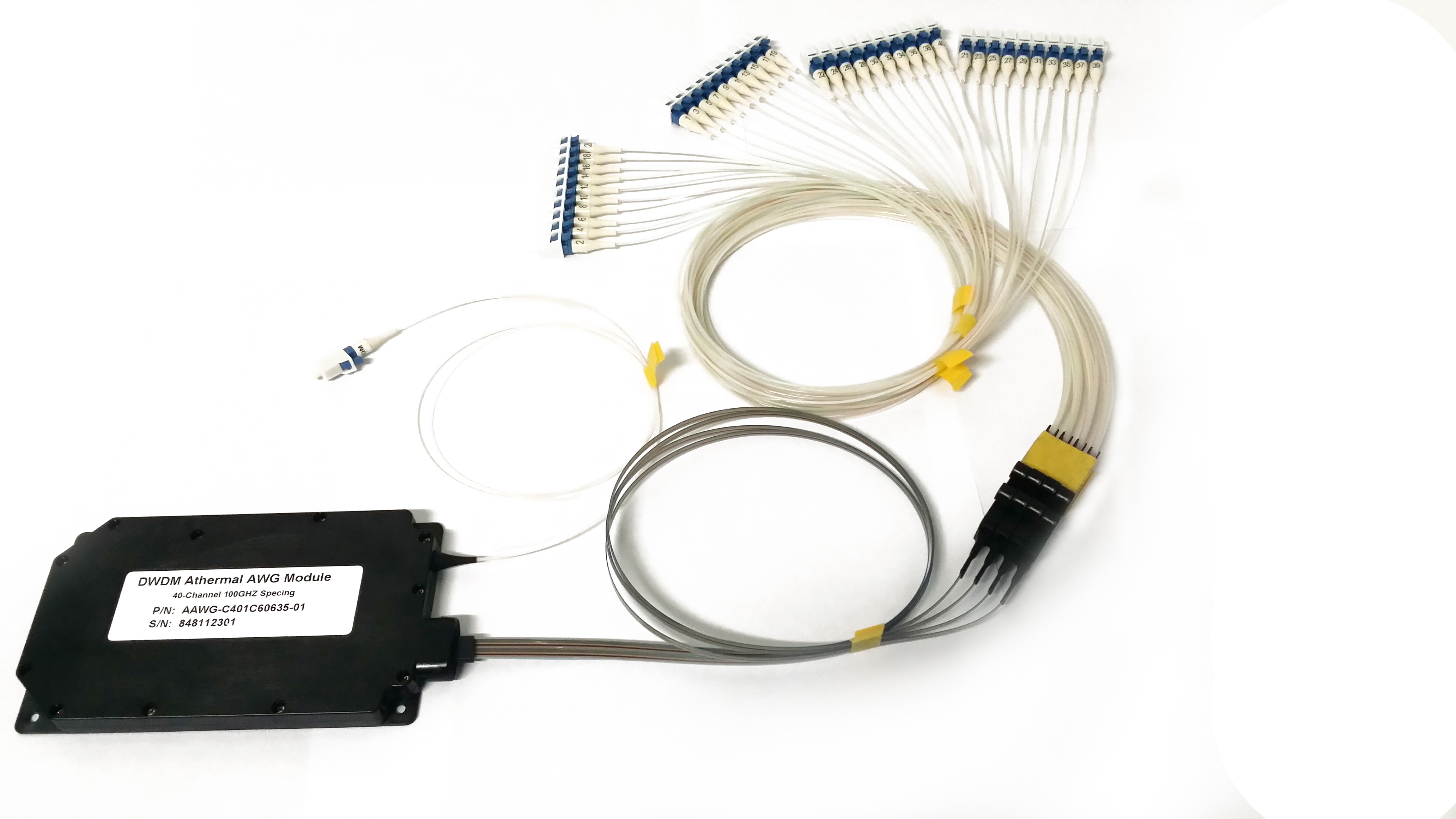
Figure 2 AAWG planar drawing
Parameters | Notes | Specifications | Units | ||
Min | Typ | Max | |||
Optical Fiber Terminations | LC/UPC | ||||
Package Size | (L*W*H) | 120*70*10 | mm³ | ||
Common Fiber Length | Including connector | L:1000±50 | mm | ||
Common Fiber Type | 900μm loose tube G652D | ||||
Fiber from module to fan-out | L1: 500±50 | mm | |||
Fiber from fan-out to connectors | Including connectors | L2: 500±50 | mm | ||
Channel Fiber Type | 900μm loose tube G652D | ||||
If you need more information, Please contact us .

 Русский