Features
Optical functional scheme
Description
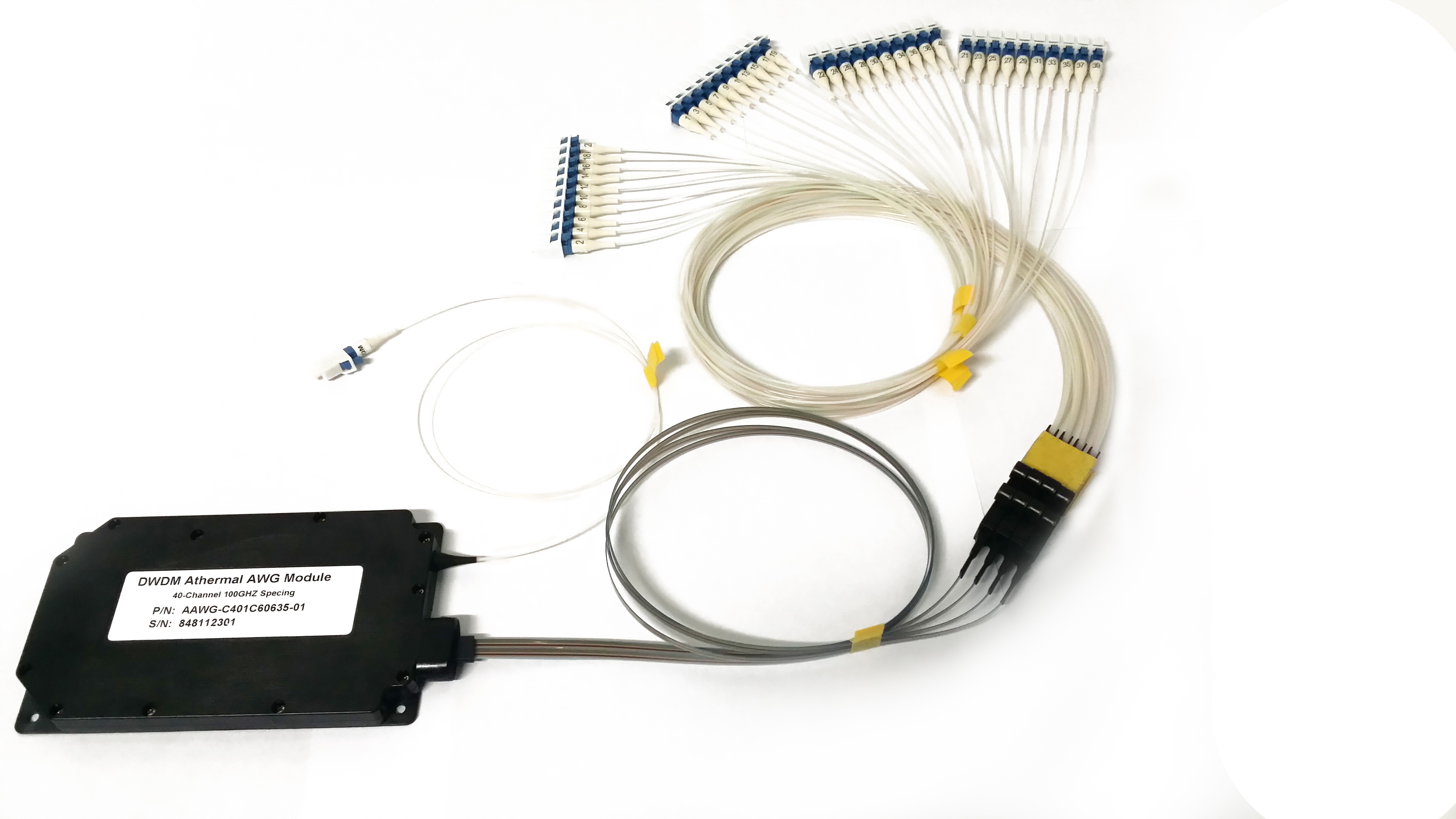
64 Channel ,75GHz Flattop AAWG
Applications
The specifications serve for C-band
AWG Flattop MUX/DEMUX in DWDM system.
Technical parameter
Absolute Maximum Ratings
Parameters | Conditions | Specifications | Unit |
Operating Temperature | Non-Condensing Environment | -5~+65 | oC |
Storage Temperature | Device Not Powered on Heater Element | -40~+85 | oC |
Optical Specifications
Wavelength Parameter | Wavelength Ranges | Units |
Center Frequency | fc | CH |
Working Bandwidth (ITU Band) -WB | fc ± 31.5 | GHz |
Isolation Bandwidth - IBW | fc ± 9.0 | nm |
Test Parameter | Channel Ports | Test Requirement | Min | Max | Units |
0.5 dB net half Bandwidth | >22.5 | GHz | |||
3 dB net half Bandwidth | >36.0 | GHz | |||
Mux/demux Insertion Loss at ITU Grid EOL | All ports at fc | To be tested | 4.0 | 6.5 | dB |
Insertion Loss Variation | All ports at ITU | To be tested | 1.5 | dB | |
Channel Isolation | Adjacent Channel, | To be tested | 13 | dB | |
Non-adjacent | To be tested | 30 | dB | ||
Return Loss | All Ports | To be tested | 36 | dB | |
Directivity | All Ports | Guaranteed by design | 45 | dB | |
PDL | All Ports over WB | To be tested | 1.1 | dB | |
All Ports @ ITU | To be tested | 0.7 | dB | ||
Differential Group Delay | All Ports over WB | Guaranteed by design | 1 | ps | |
Chromatic Dispersion (CD) | All Ports over WB | Guaranteed by design | -33 | 33 | ps/nm |
Channel Plan
ch # | Wavelength (nm) | Frequency (THz) | ch # | Wavelength (nm) | Frequency (THz) | |
1 | 1566.62 | 191.3625 | 33 | 1547.22 | 193.7625 | |
2 | 1566.01 | 191.4375 | 34 | 1546.62 | 193.8375 | |
3 | 1565.39 | 191.5125 | 35 | 1546.02 | 193.9125 | |
4 | 1564.78 | 191.5875 | 36 | 1545.42 | 193.9875 | |
5 | 1564.17 | 191.6625 | 37 | 1544.82 | 194.0625 | |
6 | 1563.56 | 191.7375 | 38 | 1544.23 | 194.1375 | |
7 | 1562.95 | 191.8125 | 39 | 1543.63 | 194.2125 | |
8 | 1562.33 | 191.8875 | 40 | 1543.04 | 194.2875 | |
9 | 1561.72 | 191.9625 | 41 | 1542.44 | 194.3625 | |
10 | 1561.11 | 192.0375 | 42 | 1541.84 | 194.4375 | |
11 | 1560.50 | 192.1125 | 43 | 1541.25 | 194.5125 | |
12 | 1559.90 | 192.1875 | 44 | 1540.66 | 194.5875 | |
13 | 1559.29 | 192.2625 | 45 | 1540.06 | 194.6625 | |
14 | 1558.68 | 192.3375 | 46 | 1539.47 | 194.7375 | |
15 | 1558.07 | 192.4125 | 47 | 1538.88 | 194.8125 | |
16 | 1557.46 | 192.4875 | 48 | 1538.28 | 194.8875 | |
17 | 1556.86 | 192.5625 | 49 | 1537.69 | 194.9625 | |
18 | 1556.25 | 192.6375 | 50 | 1537.10 | 195.0375 | |
19 | 1555.65 | 192.7125 | 51 | 1536.51 | 195.1125 | |
20 | 1555.04 | 192.7875 | 52 | 1535.92 | 195.1875 | |
21 | 1554.44 | 192.8625 | 53 | 1535.33 | 195.2625 | |
22 | 1553.83 | 192.9375 | 54 | 1534.74 | 195.3375 | |
23 | 1553.23 | 193.0125 | 55 | 1534.15 | 195.4125 | |
24 | 1552.62 | 193.0875 | 56 | 1533.56 | 195.4875 | |
25 | 1552.02 | 193.1625 | 57 | 1532.98 | 195.5625 | |
26 | 1551.42 | 193.2375 | 58 | 1532.39 | 195.6375 | |
27 | 1550.82 | 193.3125 | 59 | 1531.80 | 195.7125 | |
28 | 1550.22 | 193.3875 | 60 | 1531.21 | 195.7875 | |
29 | 1549.62 | 193.4625 | 61 | 1530.63 | 195.8625 | |
30 | 1549.01 | 193.5375 | 62 | 1530.04 | 195.9375 | |
31 | 1548.41 | 193.6125 | 63 | 1529.46 | 196.0125 | |
32 | 1547.82 | 193.6875 | 64 | 1528.87 | 196.0875 |
Note: All specifications being applicable to both MUX and DEMUX
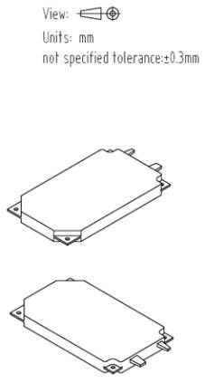
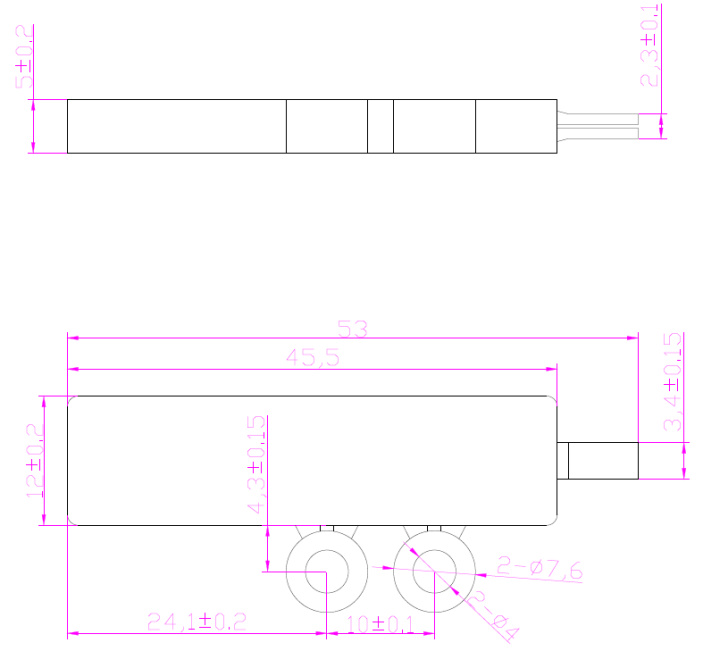
Mechanical Dimensions
PARAMETER | SPECIFICATION | UNITS | NOTE |
Packaged Size | 120×70×11 | mm | MUX or DEMUX |
![7C}~B_B2]T]Y%AN3)0E`H$I.png 7C}~B_B2]T]Y%AN3)0E`H$I.png](/uploads/20210618/202106181055215264.png)

PIGTAIL AND CONNECTOR
PARAMETER | SPECIFICATION | UNIT |
Pigtail Type (All ports) | SMF28e with 900um Loose tube fiber | |
Common Fiber | 500±50 | mm |
Ribbon Fiber | 500±50 | mm |
Fanout Fiber | 500±50 | mm |
Connector Type (All ports) | LC/UPC |


QUALIFICATION
Reliability:Compliant to Telcordia GR-1209/1221
ENVIRONMENTAL SAFETY
Compliant to ROHS6
Ordering Information: HC-AWG-A-B-C-D-E-F-G-H-J
A | B | C | D | E | F | G | H | J |
Type | Band | Number of Channels | Spacing | 1st Channel | Chip Type | Package | Fiber Length (Total Length) | In/Out Connector |
AAWG= Athermal AWG | C=C-Band L=L-Band D=C+L-Band X=Customize | 16=16-CH 32=32-CH 40=40-CH 48=48-CH 96=96-CH XX=Special | 1=100G 2=200G 5=50G X=Special | C62=C62 H61=H61 C60=C60 H59=H59 . XXX=special | G=Gaussian F=Flat Top | M=Module R=Rack X=Special | 1=0.5m 2=1m 3=1.5m 4=2m X=Specify | 0=None 1=FC/APC 2=FC/PC 3=SC/APC 4=SC/PC 5=LC/APC 6=LC/PC 7=ST/UPC X=Specify |
Note: Typical channel plan: ITU wavelengths 50G H13(1566.72nm)-C61(1528.77nm).