
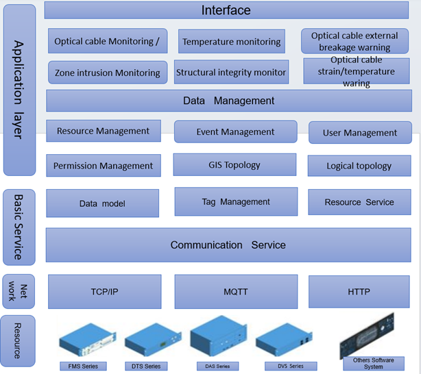
The following figure shows the system architecture of the system. The system collects the data of various resources from the communication service, and submits them to the system application layer for further analysis after basic data processing and marking. The application layer provides different application services for different data. At the same time, the northbound interface of the system supports rich protocols and can be quickly connected to other systems.
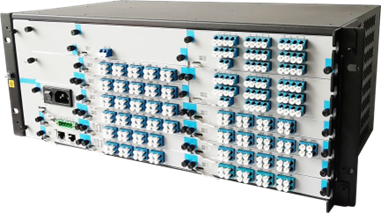
The optical cable monitoring host adopts plug-in card design, supports multiple service boards such as OTDR, optical switch and optical power monitoring, supports service fiber core and idle fiber core monitoring, and meets the requirements of non-real-time and real-time monitoring. Different boards can meet the diverse needs of users.
HC-FMS-3 Series | HC Optical Science and Tech relies on years of rich experience and understanding of online monitoring of optical cables, based on optical time domain Reflection technology, design and development of a new generation of plug-in intelligent optical cable monitoring host. The intelligent optical cable monitoring host can monitor idle fiber cores and service fiber cores, meet real-time and non-real-time monitoring, support N-to-N multi-mode optical line protection function, and provide guarantee for efficient operation of the optical network. |
The optical fiber cable monitoring system is based on optical time domain reflectometry (OTDR) technology, which is a mature and standard optical fiber sensing technology. Based on the YD/T 5066-2005 standard of the Ministry of Industry and Information Technology, HC Optical Science and Tech has developed a set of optical cable monitoring system based on BS architecture by using the scheme of optical switch gating fiber core.

System configuration requirements
Operating System | Windows 10 21H2 or later Windows server 2016 or later Linux kernel version 5.15 or later Kirin 22.04 LTS or later Galaxy Kirin (x86) V10.0-20221226. |
Database | MySQL 5.7 or higher Redis 6.0 or higher |
Web | Nginx 1.0 or higher |
Browser | 360 Browser Edge Browser |
Processor | 3.1GHz or higher |
Memory | 16GB DDR4 or higher |
Storage | 600MB @ software body, map and log are based on the actual project |
Network | 100Mbps |
Technical specification of optical cable monitoring host
Monitoring distance | ≤120km |
Dynamic range | ≤40dB |
Event blind area | ≤5m |
Attenuation blind area | ≤12m |
Monitor the fiber core | Idle core, service core, |
Monitoring mode | Polling monitoring and real-time monitoring |
Power source | DC 48V(38 ~ 58V) AC 220V(85 ~ 264V) |
Power | ≤ 50W (full load) |
Measure the time | ≤ 30s/channel @ typical value: 10s/channel |
Operating temperature | -5 ~ 55℃ |
Dimension (mm) | 1U:483 × 240 × 44 2U:483 × 240 × 88 4U:483 × 240 × 176 |
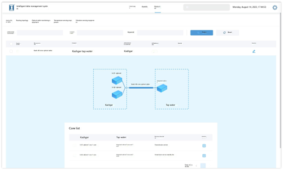
The system supports graphical display of resources accessed to the system, and users can configure and manage various resources intuitively. When the resource changes, the interface will be updated synchronously.
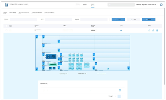
For the optical cable resource, the system can display the fiber core utilization rate, the service description of the fiber core, and the topology of the two ends of the optical cable.
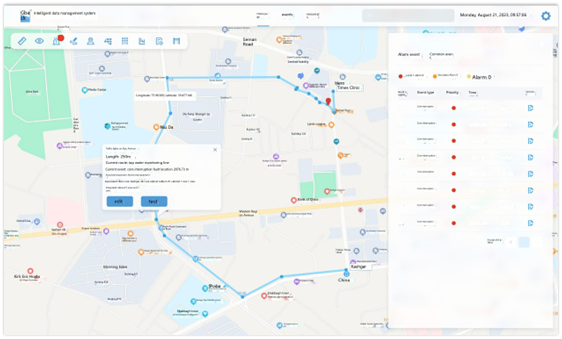
The system automatically generates the optical cable routing topology in the GIS map according to the optical cable routing (line) data. At the same time, the system can identify the location of the alarm event in the GIS map, and the user can intuitively grasp the current status of the optical cable routing.
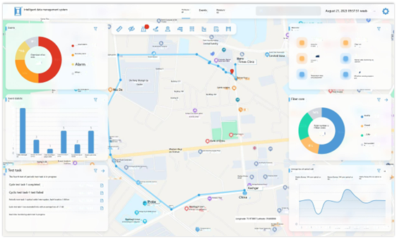
The system classifies and counts the data of all resources, and presents them in the form of charts and reports on the homepage. So that users can intuitively and accurately grasp the running status of the system and resources. At the same time, the home page supports multiple application functions, and users can easily call each resource.
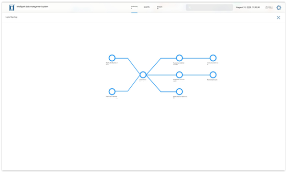
The system supports the manual drawing of the logical topology diagram of the optical cable resource. Meanwhile, the system can automatically generate the logical topology of the optical cable according to certain rules based on the input data of the optical cable resource.
![]()
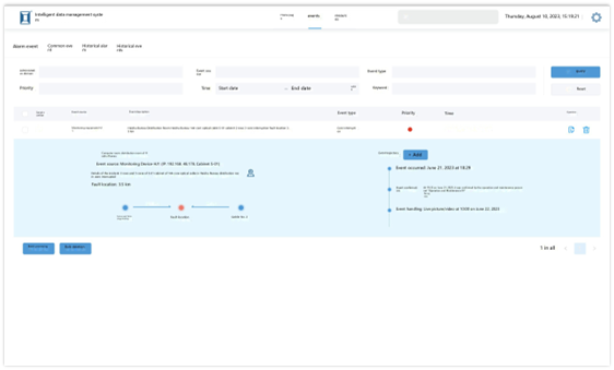
The system can record and query current and all historical alarm information. In addition, the system supports the definition of alarm rules. At the same time, the system supports the access SMS module to send the alarm to the operation and maintenance personnel in the form of SMS or email.
Core quality monitoring
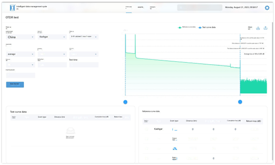
Relying on the optical cable monitoring host, the system provides users with the functions of real-time monitoring, manual testing and periodic testing of fiber core quality, which can measure the overall loss and the insertion loss and return loss of each node in the line, and calculate the average loss of the line.
Real-time monitoring | The system monitors the optical power in real time, and when the optical power of the fiber core is abnormal, it will automatically initiate the test of the fiber core immediately. |
Manual test |
The user can initiate a test for a fiber core. |
Cycle test |
Users can set up periodic test tasks to initiate tests on specific lines in a fixed period of time every day. |
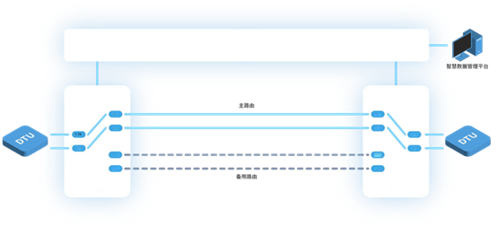
The optical cable monitoring host supports the optical line protection (OLP) service card. When the line fails, the system can automatically switch to the standby line and test the fault location to ensure the smooth communication line.
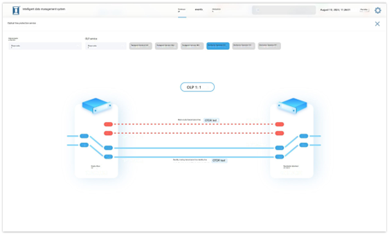
The user can grasp the operation status of the line in real time in the system interface, and can switch manually
In the engineering application, the optical cable monitoring host can monitor the idle fiber core or the service fiber core according to the requirements. It should be noted that when monitoring the service fiber core, the deployment of the relevant equipment of the optical cable monitoring system will bring an additional 2dB loss to the line as a whole, and the service needs to be interrupted for at least 2 hours during the implementation.
The optical cable monitoring host is deployed at one end of the line, and the OTDR test is started for polling monitoring after the fiber core is gated by the optical switch. Polling monitoring is the basic scheme of fiber core quality monitoring.
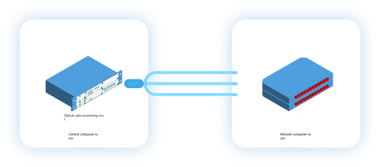
According to the YD/T 5066-2005 standard document of the Ministry of Industry and Information Technology, the optical cable monitoring host and stable light source equipment are deployed at both ends of the optical cable. Two fiber cores are selected, wherein one fiber core is used for the optical cable monitoring host to monitor the optical power of the stable light in real time, and the other fiber core is used for automatically dispatching the OTDR to test the fiber core when the optical power is abnormal so as to find out the fault position, thereby achieving the purpose of real-time monitoring.
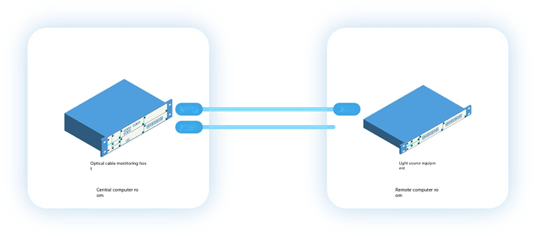
The optical cable monitoring host adopts the plug-in card design, and the light source board card can be configured on the host. Therefore, when the line is short, the line can be looped and jumpered, and the real-time monitoring can be completed only by deploying the optical cable monitoring host at one end of the line.
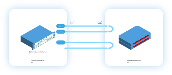
When the fiber core resource is in short supply, a combined wave and division wave board card can be configured in the optical cable monitoring host to couple the stable light source combined with the OTDR laser to one fiber core. This scenario also supports loopback deployment.
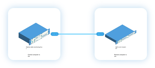
In this project, the optical cable monitoring host is deployed in the combat center to monitor each facility in the area in real time to ensure the normal communication of each facility. The data of the optical cable monitoring host is returned to the operation center and managed by the command system.
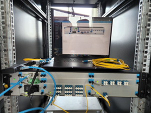
This project uses several sets of equipment to monitor more than 10000 cores in the optical cable convergence room of a certain unit in the theater.
The project is used to monitor the fiber cores of power composite cables and communication optical cables, and to inform the operation and maintenance personnel in time when the cables and optical cables fail, so as to ensure the normal operation of the power system.
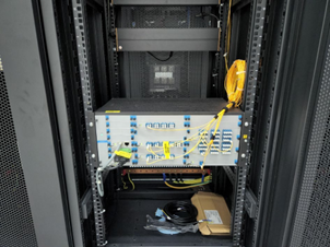
In the highway scenario, the ETC equipment of each toll station is connected by optical cable.
 This project monitors a high-speed ETC special line in Jinan, and senses the fault location in time when the ETC special line fails, so as to improve the efficiency of line operation and maintenance.
In a coal mine of Shaanxi Coal Group, the optical cable monitoring system is used to monitor whether there is a fault in the communication optical cable of each system under the mine to ensure the safety of the mine.
The optical fiber communication information network between all buildings in a university in Hubei is monitored to ensure the normal communication of the campus network.
If you need more supports , Please contact with us.