MEMS Dual 4×4 Optical Switch Matrix Module
Product Presentation
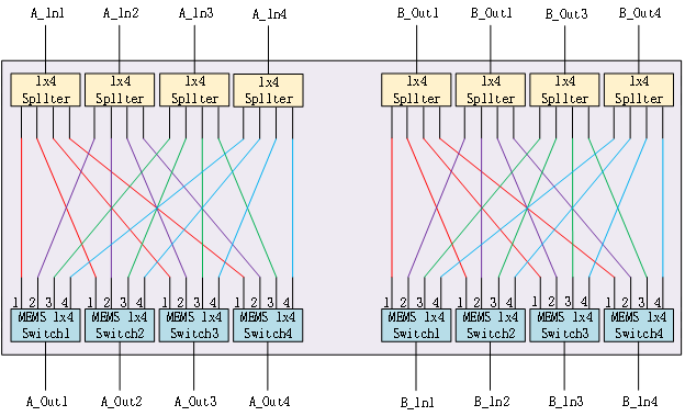
MEMS Dual 4x4 Multicast Switch is based proven MEMS 1xN Switch, and incorporates two 4x4 Multicast Switches for add/drop functionality in a single package. For the drop side, input signals are first broadcast via 1x4 optical splitters into 4 optical switches, which are then used to independently route network traffic from any input to any or all output ports. For the add side, each switch receives an input and selects one of the N splitters to receive traffic for broadcast to the network. The MEMS Dual 4x4 Multicast Switch is ideal for colorless, directionless and contentionless add/drop multiplexing.
Feature

Technical Parameter
|
Product Number |
MEMS-Dual 4×4-MCS-M |
|
Fiber Type |
SM(9/125) |
|
Wavelength Range |
1550nm |
|
Insertion Loss |
≤8.0dB |
|
Wavelength Dependent Loss |
≤0.5dB |
|
Polarization Dependent Loss |
≤0.5dB |
|
Return Loss |
≥40 dB |
|
Crosstalk |
≥50 dB |
|
Repeatability |
≤±0.05dB |
|
Switching Time |
≤15ms |
|
Durability |
≥109 cycles |
|
Connector Type |
FC/PC |
|
Pigtail Length |
1.0m |
|
Optical Power |
≤500 mW |
|
Power Supply |
5V / 250mA |
|
Working Temperature |
-5 ~ 70 °C |
|
Storage Temperature |
-40 ~ 85 °C |
|
Packaging Dimensions |
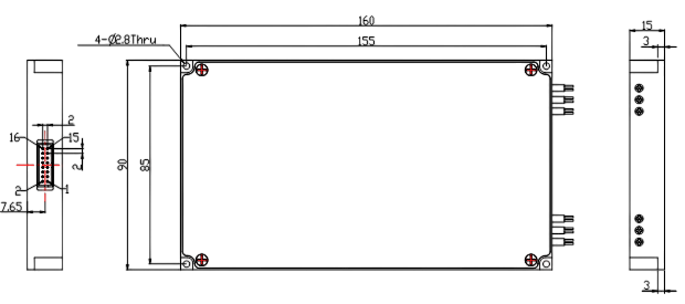
90(L) x 160(W) x 15(H) ±0.2mm |
Dimension(mm)

Electrical-pins definition
|
PIN |
Definition |
Signal |
Function |
|
1 |
NC |
No physical internal connection |
|
|
2 |
NC |
No physical internal connection |
|
|
3 |
VCC |
Power |
Power supply, 5V/0.25A |
|
4 |
NC |
No physical internal connection |
|
|
5 |
NC |
No physical internal connection |
|
|
6 |
GND |
Power |
GND |
|
7 |
NC |
No physical internal connection |
|
|
8 |
SDA |
I/O |
I2C DATA |
|
9 |
TXD |
Output |
RS232: Transmit Data; |
|
10 |
RXD |
Input |
RS232: Receive Data |
|
11 |
SCL |
I/O |
I2C CLK |
|
12 |
NC |
No physical internal connection |
|
|
13 |
NC |
No physical internal connection |
|
|
14 |
NC |
No physical internal connection |
|
|
15 |
NC |
No physical internal connection |
|
|
16 |
NC |
No physical internal connection |
Factory default configuration
|
Item |
Factory default configuration |
Note |
|
Serial baud rate |
115200 |
8 data bits, 1 stop bit, no parity |
|
Working channel |
In1→Out1、In2→Out2 In3→Out3、In4→Out4 |
Group A and group B are the same optical path identification |
If you need any support , Please contact us.


