2U Rackmount 48x48 Optical Switch
Product Introduction
Optical switch is an optical path control device that plays the role of controlling and converting the optical path. It plays an important role in optical communication applications.
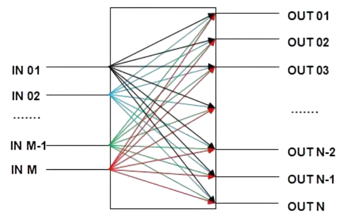
48x48 optical switch can be 48ports input route to select the switch to the 48 output routes.
Product Characteristics
Ø Low insertion loss and fast switching speed.
Ø TFT screen display, which is very intuitive to show the data and convenient for user's operation.
Ø Support to set with automatically scan by the set "start channel" and "end channel" by setting the interval time.
Ø Support communication with through USB, RS23 serial port and RJ45 internet port.
Ø Support to set serial port baud rate and USB baud rate according to the actual situation, following baud rates are available: 4800, 9600, 14400, 19200, 38400,
56000, 57600, 115200, 230400, 460800, 512000, 600000, 750000, 921600, 1000000.
There are fifteen kinds of baud rates.
Technical Parameters
|
Parameters |
Unit |
Specification |
|
Model |
-- |
OXC-48×48-SM |
|
Channels |
CH |
48x48 |
|
Working Wavelength |
nm |
1260-1650 |
|
Testing Wavelength |
nm |
1550 |
|
Insertion Loss (Max) |
dB |
3.2(Including Connectors) |
|
Return Loss |
dB |
≥55 |
|
Crosstalk |
dB |
≥45 |
|
TDL |
dB |
≤0.6 |
|
PDL |
dB |
≤0.30 |
|
Repeatability |
dB |
≤0.03 |
|
Response Time |
ms |
≤70 |
|
Durability |
Cycle |
≥1×10⁹ |
|
Drive Voltage(Max) |
V |
220V(50/60Hz) |
|
Power Consumption |
W |
≤20 |
|
Control Type |
Ethernet/RS232/USB |
|
Size |
483*250.2*89mm |
Note:
1. The loss is based on the test results at 23℃.
2. Repeatability is defined after 100 cycles.
Use Instruction
4.1. Structural Schematic Description
4.1.1. Front Panel Description
Front Panel

1) TFT screen:Display of device address, current channel and related information.
2) ▲——Up ;▼——Down ;Enter——OK;Esc——Cancel.
3) Power indicator light-Power:Display of power supply.
4) Optical Interface Description:The I/O ports on the device panel are public ports, and IN1, 2, 3, ......IN48, and OUT1,2,3....OUT48 are the respective channel numbers.
4.1.2. Back Panel Description
Back Panel

1) AC or DC power supply interface: the input interface for the working power supply of the device.
2) RJ45 Ethernet interface, USB square female connector, RS-232 (DB9 female) interface: communication interface for equipment monitoring data information.
3) Binding post: External grounding post.
4.2. Device Connection Instructions
4.2.1. Internal Optical Path Description

48×48 optical switch internal optical path description
4.2.2. Communication Interface Connection Description
1) RS-232 interface: when equipment and computer connection, use the USB to RS232 (DB9 male) serial cable to connect. Namely the two ends of the # 2, # 3 pins are connected to the cross, the two sides of the # 5 pins butt, the rest of the pins cannot be connected
2) USB interface: when equipment and computer connection, connect the USB2.0 square port data cable to the USB square female connector of the equipment.
3) RJ45 Ethernet interface: when equipment and computers connected through the switch, use the of straight-through line (both sides of the wiring order are: 1-orange white, 2-orange, 3-green white, 4-blue, 5-blue white, 6-green, 7-brown white,
8-brown); when equipment and computers directly connected , you should use the crossover line (one side of the line is: 1-orange white, 2-orange, 3-green white,
4-blues, 5-blues, 6-greens, 7-brown white, 8-brown) -green, 7-brown white,
8-brown; at the other side: 1-green white, 2-green, 3-orange white, 4-blue, 5-blue white, 6-orange, 7-brown white, 8-brown).
If you need more support , Please contact us .


