1×4 PM Magnet Optical Switch
Product Description
The μs-series 1x4 PM solid-state fiber optical switch connects optical channels by redirecting an incoming optical signal into a selected output optical fiber. The switching of the optical light is realized by utilizing Faraday Effect.
This is achieved using a patent protected non-mechanicalconfiguration with solid-state all-crystal design whicheliminates the need for mechanical movement. Theμs-series fiber optic switch is designed to meet the mostdemanding switching requirements of reliability, durability,response, and continuous high frequency switching operation.
Features
Ultra fast switching speed
Extremely stable latching mode
No moving parts,best durability
Exceptional reliability and stability
Easy to route -all fibers on sameside
Applications
Optical switching
System monitoring
Test & measurement
High speed protection
Fiber-opticssensingsystem
Technical Parameters
|
Item |
Unit |
Parameters |
Notes |
|
|
Unidirectional |
Bidirectional |
|||
|
Wavelength Range |
nm |
1525~1565 |
||
|
Insertion Loss |
dB |
1.0(Typ.); 1.5(Max.) |
1.0(Typ.);1.8(Max.) |
|
|
Return Loss |
dB |
≥40(Typ.50) |
≥30(Typ.40) |
|
|
Crosstalk |
dB |
≥30(Typ.40) |
≥30(Typ.40) |
|
|
ER |
dB |
≥18 |
||
|
WDL |
dB |
≤0.3 |
||
|
TDL |
dB |
≤0.3 |
||
|
Repeatability |
dB |
+/- 0.01 |
||
|
Durability |
cycles |
Regular (>100Billions), Ultra-fast (>1000Billions) |
||
|
Switching Speed |
μs |
Regular (50~200), Ultra-fast (2~20) |
||
|
Operating Temperature |
°C |
-5~70 |
||
|
Storage Temperature |
°C |
-40~85 |
||
|
Maximum Optical Power |
mW |
500 |
||
|
Dimension( L×W×H ) |
mm |
37×21x7.5 |
||
*.All the specifications are based on the devices without connector, and guaranteed over wavelength, polarization and temperature.
**.Specifications are subject to change without notice.
Electrical Specifications
|
Parameters |
Specifications |
Unit |
|
|
Regular |
Ultra-fast |
||
|
Switching Speed |
50~200 |
2~20(Typ.5) |
μs |
|
SwitchingVoltage (VCC) |
3(+/-5%) |
3-7.5 |
V |
|
Switching Current |
< 100 |
< 350 |
mA |
|
Driving Mode |
Voltage or Pulse Driving |
Pulse Driving |
NA |
|
Pulse Width (typical) |
300(Typ.);500(Max.) |
20 |
μs |
|
Claim Frequency |
<1000 |
<3500 |
Hz |
Bidirectional Pin Definition
|
Pin No. |
Pin1 |
Pin2 |
Pin3 |
Pin4 |
Pin5 |
Pin6 |
Pin7 |
Pin8 |
|
IN ↔ OUT1 |
+ |
- |
+ |
- |
— |
— |
— |
— |
|
IN ↔ OUT2 |
- |
+ |
- |
+ |
— |
— |
— |
— |
|
IN ↔ OUT3 |
+ |
- |
- |
+ |
— |
— |
— |
— |
|
IN ↔ OUT4 |
- |
+ |
+ |
- |
— |
— |
— |
— |
Unidirectional Pin Definition
|
Pin No. |
Pin1 |
Pin2 |
Pin3 |
Pin4 |
Pin5 |
Pin6 |
Pin7 |
Pin8 |
|
IN→OUT1 |
+ |
- |
+ |
- |
— |
— |
— |
— |
|
IN→OUT2 |
- |
+ |
- |
+ |
— |
— |
— |
— |
|
IN→OUT3 |
+ |
- |
- |
+ |
— |
— |
— |
— |
|
IN→OUT4 |
- |
+ |
+ |
- |
— |
— |
— |
— |
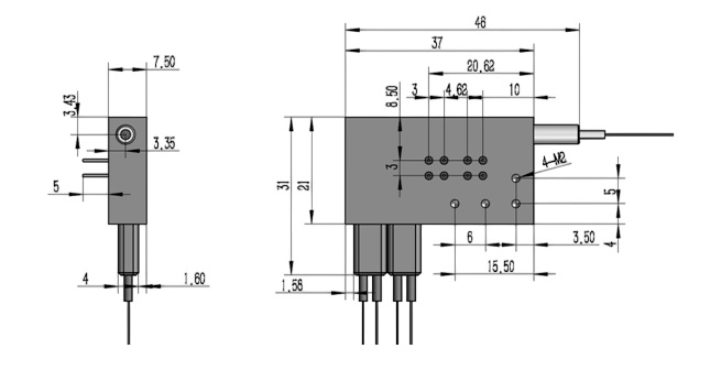
Dimensions Drawing (mm)

Ordering Information: HC-14PMMN-A-B-C-D-E-F-G-H
|
14PMMN- |
A |
B |
C |
D |
E |
F |
G |
H |
|
Working Mode |
Switching Speed |
Operating Wavelength |
Axis Type |
Fiber Type |
Fiber Tuber |
Fiber Length |
Connector Type |
|
|
1.Regular 2.Bidirectional
|
1.50~200us 2.2~20us 3. Others |
1.CBand 2. L Band 3. C & L Band 4. Others
|
1.B(Both of axis working) 2.F (Fast axis blocked) |
1.PM15 2.PM98 3.PM13 4.Others |
1.250μm fiber 2. 900μm fiber 3. Others |
1.0.5 +/- 0.1 m 2. 1.0 +/- 0.1 m 3. Others |
0.None 1. FC/UPC 2. FC/APC 3. SC/UPC 4. SC/APC 5. LC/PC 6. MU/PC 7. Others |
If you need more support , Please contact us .


