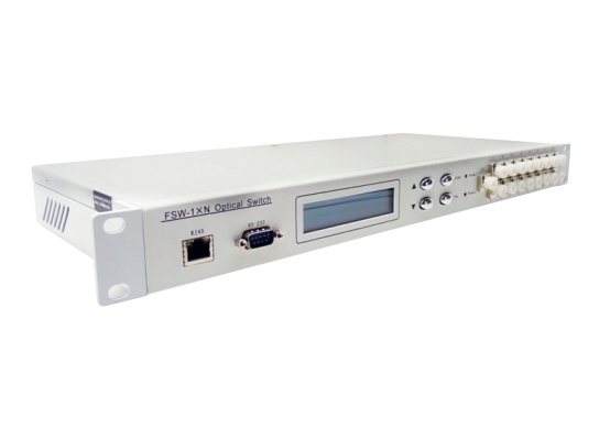
Rack-Mounted 1 × N Multimode Optical Switch
1. Product Introduction
Optical switch is a kind of optical path control device, which plays the role of controlling and converting the optical path. And play an important role in optical communication application. The optical switch is mainly used in multi-channel optical monitoring, LAN multi-light source/detector automatic switching and optical sensing multi-point dynamic monitoring system in the optical transmission system, optical fiber, optical device, network and field engineering optical cable test in the optical test system; Optical device assembly and adjustment. The 1 × N optical switch can switch one input route to one of N output routes.
2. Product Features
Ø It has the characteristics of low insertion loss and fast switching speed.
Ø The LCD display screen is used to display data intuitively and facilitate the user's operation.
Ø Automatic scanning can be set, and the maximum switching interval is 99 hours, 59 minutes and 59 seconds; You can also set the Start Channel and End Channel of the scan.
Ø The "device address" can be set to facilitate the user to use one serial port to control multiple optical switch instruments in the case of shortage of serial port resources.
3. Technical Parameters
|
Model |
HC-FSW-MM-1XN -1U/2U |
|
Operating wavelength |
850 nm |
|
Test wavelength |
850nm |
|
Insertion loss |
≤1.2 dB |
|
Repeatability |
≤±0.05 dB |
|
Return loss |
≥30dB |
|
Crosstalk |
≥30dB |
|
Wavelength dependent loss |
≤0.25 |
|
Switching time |
≤ 10 ms (adjacent sequential switching) |
|
Fiber type |
MM(50/125um)OM3 |
|
Connector form |
FC/PC |
|
Monitoring port |
RJ45、RS-232 |
|
Working power supply |
Single AC: 85 ~ 264 (50/60Hz) |
|
Operating temperature |
-5 ~ + 60℃ |
|
Storage temperature |
-40 ~ + 80°C |
|
Chassis type |
19-inch standard 1U rack (483 × 220 × 44mm) |
4. Instructions for Use
4.1. Schematic Description of the Structure
4.1.1. Front Panel Description
Front panel

(1) LCD display screen: display of equipment address, current channel and relevant information.
(2) ▲-Move up key; ▼-Move down key; Enter-Confirm key; Esc-Cancel key.
(3) Power indicator lamp Power 1, Power2: working power indicator.
(4) Optical interface description: I/O ports on the equipment panel are public ports, 1, 2, 3, … … 24 is the number of each channel.
4.1.2. Rear Panel Description
Rear panel

(1) RJ45 Ethernet interface, RS-232 serial port: communication interface for equipment monitoring data information.
(2) AC power interface: AC power input interface for equipment operation.
4.2. Device Connection Instructions
4.2.1. Schematic Description of Internal Optical Path

Schematic diagram of internal optical path of 1 × 24 optical switch
4.2.2. Description of Communication Interface Connection
(1) RS-232 interface
When connecting the device to a computer, you should use a serial port crossover cable with a hole DB9 at both ends. That is, the # 2 and # 3 pins at both ends are crossed and connected, the # 5 pins at both ends are butted, and the other pins may not be connected.
(2) RJ45 Ethernet interface
When the equipment is connected to the computer through the switch, the straight-through line should be used (the wiring sequence at both ends is: 1-orange white, 2-orange, 3-green white, 4-blue, 5-blue white, 6-green, 7-brown white, 8-brown); When the device is connected directly to the computer, a crossover wire should be used (one end: 1-Orange-White, 2-Orange, 3-Green-White, 4-Blue, 5-Blue-White, 6-Green, 7-Brown-White, 8-Brown; the other end: 1-Green-White, 2-Green, 3-Orange-White, 4-Blue, 5-Blue-White, 6-Orange, 7-Brown-White, 8-Brown).
If you need more support , Please contact us .


